The New Current War: The Isolated vs. Non-Isolated DC:DC Converter
An explanation of the two main types of DC:DC converters and their applications and relative merits
The power distribution business of the late 19th century was dominated by the now infamous “War of the Currents” between Thomas Edison and Nikola Tesla. The battle was epic and has been subject of numerous books and even a recent Hollywood major motion picture. However, as we rocket toward the middle portion of the 21st century, we are seeing DC make a major resurgence as two major DC power elements, solar and battery energy storage, become a more important part of our energy mix. The reemergence of DC is creating a new current war of sorts, a conflict between two approaches to translating DC power to accommodate the need for different levels of DC voltage between source and load, a process known as DC:DC conversion.
Today’s commercial and utility scale DC:DC converters have a variety of applications, from pairing solar and storage on the DC side of the inverter to increasing or decreasing the level of voltage generated from solar to accommodate certain DC loads. Needless say, they are often at the heart of a number of modern microgrids.
DC:DC converters, or DC:DC optimizers, as they are sometimes called, can be built in one of two ways:
1. Isolated: DC input isolated from output
2. Non-isolated: DC input and output are connected to the same potential. These types of DC:DC converters are typically known as Buck, Boost or Buck-Boost converters
The isolated type of DC:DC converter, the category to which Alencon’s SPOT and BOSS devices belong, can be particularly advantageous over the non-isolated type for a number of reasons, including:
1. They isolate the grounding between input and output – meaning the grounding scheme of the DC source can be different from the load on the output
2. They can “map” significantly different levels of DC voltage on the input relative to the output
3. They have very low capacitance on their output, which more readily and safely allows multiple, isolated DC:DC converters to be placed in parallel on the same DC bus
Later in this article, we will explain why these benefits matter for some of today’s most in-demand alternative energy applications. However, before doing so, we will quickly explain the operating principles behind both the isolated and non-isolated type of DC:DC converters.
The Non-Isolated Buck/Boost Converter
As its name implies, a boost converter is a DC:DC converter that boosts or increases voltage on its output relative to its input. A buck converter by contrast decreases voltage on its output relative to its input. Some devices are only boost converters, others only buck. Others are a combination of the two, meaning a single device can both increase or decrease voltage on its output relative to its input depending on the requirements. These “combined” devices are referred to as Buck-Boost converters, i.e. they combine buck and boost functionality into a single circuit.
The operating principle of a non-isolated boost converter is such that incoming energy is stored up in an inductor for a period of time and then released into a capacitor on the device’s output. This storage and release of energy is analogous to how potential energy is stored in a projectile when a sling shot is pulled back and then released. In the case of the release, the energy is stored in a capacitor before being released into the load connected on the output.
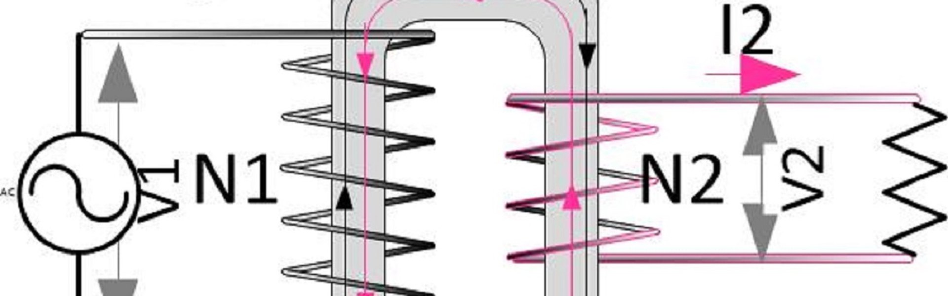
The other approach to DC:DC conversion is the isolated converter. In this approach DC current is inverted into AC and passed through a transformer and the rectified back out to an altogether different level of DC voltage. The construction, or windings, of the transformer act like gears with respect to manipulating the voltage on the input to the output. This means the ratio of the DC voltage on the input of the device relative to the output can be easily be changed by just varying the transformer construction.
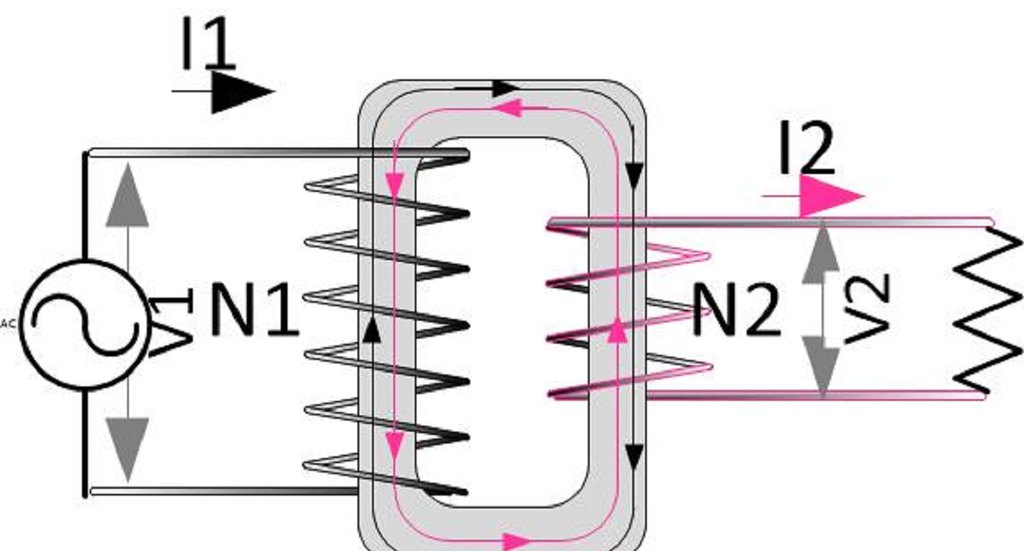
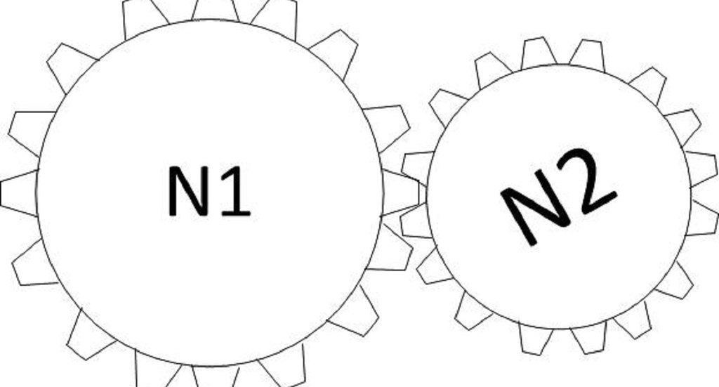
Figure 1: The drawings above illustrate the electrical princpal of a trasnformer. A transformer works electrically in much tjhe same way as gears do mechanically.
A transformer is an electrical device consisting of at least two inductor coils wound on a ferromagnetic core. A transformer is of course typically associated with AC applications, not DC applications. However, applying a transformer in a DC device by just adding a couple extra conversions offers several benefits, including isolating the ground of the input and output, a term known as galvanic isolation. Also, by relying on transformer windings, such a device can draw on one of the great benefits Tesla used to outduel Edison so many years ago – the flexibility a transformer offers in significantly changing the voltage levels.
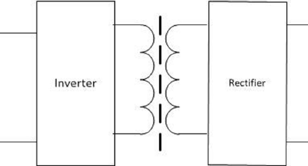
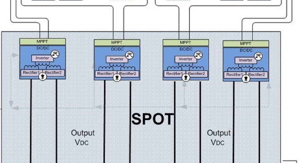
Figure 2: Galvanic isolation is used where two or more electric circuits must communicate, but their grounds may be at different potentials. Alencon Systems’ DC-DC converters consist of an inverter and a rectifier section with an isolation transformer between them to achieve full galvanic isolation between input and output. The application of silicon carbide power electronics allow Alencon’s devices to be very efficient and small.
Why the Benefits of the Isolated DC:DC Converter Matter So Much
The flexibility offered by the isolated DC:DC converter provide some very relevant benefits to a number of the major challenges found in the alternative energy field today. The isolation of grounds these devices offer is critical when marrying grounded PV systems with floating loads such as batteries or transformerless inverters (or both, as can be the case in DC coupled solar plus storage projects). There is great value in grounding PV panels as this can avoid conditions such as potential induced degradation (PID) that have proven to significantly reduce PV yield over the life of a solar project. On the load side, large scale battery energy storage systems need to float to ensure their built-in safety systems work as designed. By allowing batteries to float, it takes two leakages to ground to cause a ground fault. Unimpeded, undetected ground faults have proven to be the cause of some of the industry’s worst battery fires. Thus, detecting the first leakage to ground is a key to maintaining the safety of energy storage systems.
Additionally, the isolated DC-DC converter’s approach allows for sources and loads with large differences in DC voltages to be combined seamlessly. This can be helpful when charging batteries from solar panels that have very large differences in DC voltage. This can also be required when attaching higher voltage inverters to lower voltage solar panels in cases when older, failed inverters need to be replaced as part of a PV plant repowering exercise.
Additionally, as storage systems grow ever larger, the ability to install many DC-DC converters in parallel safely is needed to develop ever larger battery energy storage. The large amount of capacitance found on the output of non-isolated buck-boost converters can create safety challenges when many units are placed in parallel on the same DC-bus. Putting large amounts of capacitance generates a lot of energy to discharge in the event of a short, also known as fault current.
Of course, the isolated DC:DC converter is not without its challenges. The first concern many see are the potential losses in conversion efficiency from the number of transformations from DC to AC and back to DC. Fortunately, in Alencon’s case, we have been able to successfully mitigate these losses using cutting-edge power electronics based on silicon carbide (SiC) as opposed to the more traditional silicon components found in other manufacturers’ devices. Cost can also be a consideration. Fortunately, here at Alencon, we have also managed to value engineer our products such that their price is very much on par with non-isolated devices while providing the unique advantages list above.