
Reducing Fault Currents in Battery Storage and Hybrid DC Power Projects
How Alencon’s unique DC:DC converter technology helps reduce fault currents to let you build bigger, safer battery energy storage connected projects
In an earlier blog, we talked about how rack level DC converters can minimize fault currents in energy storage systems. In this article, we’ll dive yet deeper into the subject of fault currents in battery energy storage systems (BESS). This blog explains how Alencon’s cutting edge DC:DC converters can reduce fault currents in energy storage and other DC-based energy systems. Reducing the fault currents in your projects will allow you to build larger, safer BESS and “storage plus” projects than you can when employing traditional buck-boost DC:DC converters based on more traditional power electronics technologies. The techniques discussed here can also be employed when just connecting BESS systems directly to an inverter for stand-alone or AC coupled storage systems.
What is Fault Current and Why Should You Care?
Fault current is the electrical current which flows through a circuit during an electrical fault condition. A fault condition occurs when one or more electrical conductors short to each other or to ground. Electrical devices such as inverters are typically rated to withstand a certain level of fault current, meaning the sum of the fault current of the circuits connected to the inverter shall not exceed this rating.
In PV only projects, fault current limits are much less of a sizing concern than with projects that include batteries. This is because the fault current of solar panels typically (referred to as Isc on a PV panel spec sheet) are not much higher than the maximum operating current (Imp) of a PV panel.
In the world of battery energy storage systems, this is a very different situation. Batteries store a great deal of energy and thus can release a very high level of fault current into a DC bus in the event of failure. This level of fault current contribution needs to be considered when sizing power electronics like inverters for battery energy storage systems.
With battery systems increasing in duration and the trend to hybridizing systems with multiple DC sources and loads like solar, batteries, fuel cells and electric vehicles on the same DC bus, calculating fault current contribution is a major factor in determining how to build such systems safely.
Accounting for Fault Current in Hybrid DC Energy Systems
The demand for power generated and consumed by systems including solar, batteries, fuel cells and electric vehicles is accelerating as we transition to a clean energy economy. As these clean power sources are all based in DC, the desire to combine these systems without converting to AC is also growing rapidly. Afterall, doesn’t it just make sense to connect DC sources and loads without doing unnecessary DC to AC back to DC conversions? Such combinations are typically achieved by creating a common DC bus, a conductor to which multiple DC sources and loads are attached. This technique is also sometimes referred to as “DC coupling.” Today, the most common DC coupled application is the combination of solar and battery energy storage, though combining fuels cells and batteries or electric vehicles and batteries is also growing in popularity.
When multiple DC sources and loads are present on the same DC bus, typically there is at least one DC:DC converter present in the system. The role of the DC:DC converter is to match the DC current and voltage of one of the DC sources or loads to the others attached the same DC bus.
Picking the Right DC:DC Can Help You Reduce Fault Current Contribution
Each power device connected to a DC bus will make its own fault current contribution to the system. An engineer designing or approving the system for deployment will typically evaluate such fault current contributions when sizing overcurrent protection devices like fuses and determine if the components selected in the system can even safely coexist.
The challenge with hybrid DC systems, like DC coupled Solar + Storage systems, is that the need for the addition of a DC:DC converter can exacerbate the problem, depending on which type of DC:DC converter you chose.
Today, a number DC:DC converters belong to category of “buck boost” converters. Most of the larger buck boost converters on the market today, devices in the 250 to 500 KW power range, are built with IGBT switching devices. The combination of the buck-boost topology and IGBTs is a particularly bad one when it comes to fault current contribution. Buck-boost converters do not isolate the source from the load. This means that the fault current of the source device like a battery can ‘shoot through’ the buck-boost unit if fuses do not react fast enough during a fault event. Making matters worse, buck boost converters typically have a great deal of instantaneous energy they store in large capacitors on their output. Buck boost converters based on IGBTs switch at lower frequency, thus they tend to have larger bulk capacitors on their output which store a great deal of energy. This means they have a large amount of capacitance, capacity for storing instant energy. Capacitance is measured farads. Some basic engineering formulas will allow you to use capacitance to quickly calculate the fault current contribution of a given switching device like a DC:DC converter. In short, the higher the capacitance, the higher the fault currently contribution of the device.
Here at Alencon, we manufacture unique, galvanically isolated DC:DC converters that are built on a next generation, silicon carbide power electronics platform. Silicon carbide devices switch at very high frequency, far faster than traditional IGBTs. Switching faster increases conversion efficiency and shrinks the size of all the other power electronics in the system including output capacitors.
As a result, Alencon’s unique DC:DC converters can solve both of the challenges in hybrid DC systems presented when using non-isolated, buck boost converters. Since Alencon’s devices are isolated, they eliminate any “shoot through” current from the principal DC device such as a battery, thus removing the fault current contribution to the rest of the system. In practical terms, what this means is that your “worst case” scenario in the event of a battery fault like the ones that have become infamous from incidents in South Korea, Arizona, Germany and the UK is that your DC:DC converter will be damaged, though even that is unlikely since our products come integrated with fast acting fuses.
The Alencon BOSS comes fitted with a device called a FEED – the fused electrical disconnect – which includes appropriately rated fuses to protect the device from any overcurrents in the event of a fault. The BOSS also has overcurrent protection built into its circuitry to immediately disconnect from the system in the event of an electrical fault, so even the likelihood of equipment damage in the event of a fault is minimized.
On the output side, Alencon’s DC:DC converters offer minimal fault current contribution, typically having only 12 microfarads (measured as µF) for each 100 KW worth of DC:DC power conversion. As a result, using Alencon’s unique DC:DC converter in your next battery energy storage or hybrid DC project can significantly reduce the amount of fault current contribution onto the DC bus.
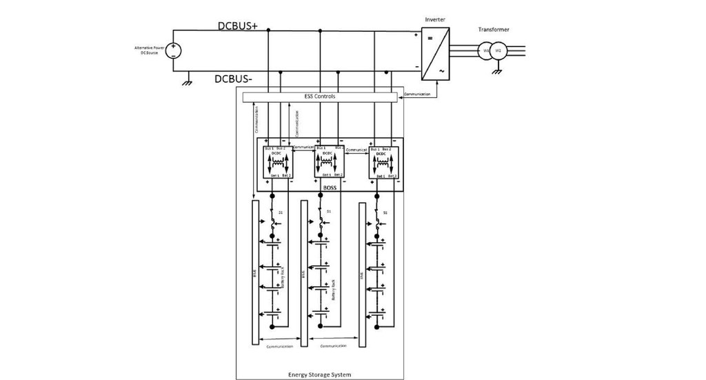
Figure 1: Placing an Alencon BOSS between batteries and a DC bus will significantly reduce the fault current contribution to the system by eliminating “shoot through” current and because the BOSS units have minimal capacitance on their output as a result of the high frequency switching technique they use.
So How Can Having Less Fault Current Help You?
Having less fault current present on a DC bus will of course increase the safety of your next battery energy storage or hybrid DC energy project. It will also reduce the cost of additional safety equipment you need to provide. The ability to reduce fault current can also allow you to put more batteries behind a DC bus or an inverter, which can be critical in building the long duration energy storage systems we need to make the transition to a clean energy future. Additionally, if you are looking to add battery energy storage to an existing PV array where the inverter is already present, you may have a cap on the fault current you can contribute to the existing inverter. As a result, selecting the right DC:DC converter technology could be the difference maker in allowing you to safely deploy your next clean energy project or perhaps not even doing so at all.
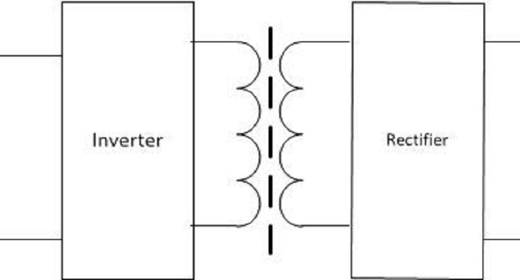
Figure 2: Alencon’s DC:DC achieve galvanic isolation through the placement of a unique, high frequency transformer between the input and the output. This isolation eliminates any “shoot through” fault current contribution from a battery.
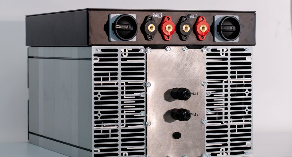
Figure 3: The Alencon BOSS comes fitted with a device called a FEED – the fused electrical disconnect – which includes appropriately rated fuses to protect the device from any overcurrents in the event of a fault. The BOSS also has overcurrent protection built into its circuitry to immediately disconnect from the system in the event of a electrical fault.