
Got PID?
How potential induced degradation lowers PV production and what you can do about it
PID. It almost sounds like a venereal disease. In a sense, it is just that for solar panels. PID stands for potential induced degradation.
First described by NREL in 2005, PID exhibits itself by significantly reducing power production from affected PV panels. The PID effect on the PV IV curve is shown in Figure 1 below. For those familiar with IV curve traces, you can see that not only does PID reduce the power output of impact PV panels, but it can also increase the amount mismatch in a PV array, thus making MPPT algorithms much less effective. (You can learn more about MPPT by clicking here)
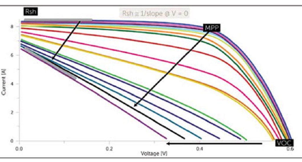
Figure 1: IV curves of PV panels affected by PID
Further research established that PID is caused by improper voltage applied to the PV cells relative to the grounded module frame and front glass. The positively-doped silicon cells (p-type cells) should be grounded negatively and negatively-doped silicon cells (n-type cells) should be grounded positively. If the voltage is reversed, the leakage current can corrode the silicon material. The process is intensified at elevated temperature and humidity. Not all PV modules are prone to PID. Primarily, it happens with modules that use front glass covers containing sodium.
Who is Affected by PID?
PID has been observed most prominently in the North American and European PV markets, but for very different reasons.
North American Situation
Most of the solar systems built five to ten years ago were built with 600 v modules and 600 v inverters, where those inverters had an internal transformer. Strings of p-type modules were grounded negatively (see Figure 2) and the strings of n-type modules were grounded positively.
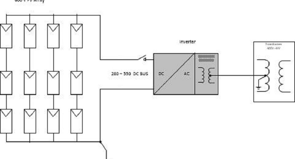
Figure 2: 600 v PV system with 600 v inverter and internal isolation transformer
The inverter’s internal transformer steps up the output voltage of the inverter from 208 volts AC to the distribution voltage of 480 volts AC and isolates the PV’s ground from the distribution transformer ground with the neutral grounded as specified by code.
However, at least one American inverter company (Advanced Energy, now supported by Bold Renewables), sold many 800-volt transformer-less inverters. These inverters required bi-polar PV arrays with a ground connected in the middle as shown in Figure 3).
In this arrangement, the lower half of the array is positively grounded, and the upper half of the array is negatively grounded. If array is built with p-type modules, the lower half may be subject to PID. Conversely, if the array is built with n-type modules, then the upper half may be subject to PID. The PV array is connected to the inverter via a device called a “PV tie.” This device monitors the balance of voltages between the two halves of the array. If the difference exceeds 200 V the device would disconnect the PV from inverter and stop generating power. This happens when half of the PV array begins to develop PID.
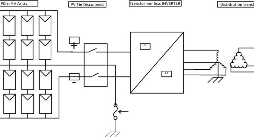
Figure 3: Advanced Energy transformer-less inverter with bi-polar PV array.
European Situation
In Europe, 1000 V PV modules were approved for use much earlier than in the US. As a result, most inverters are transformer-less, as they did not need a transformer to produce standard AC distribution voltage. In these, the array PV arrays were left ungrounded or “floating” (see Figure 4).
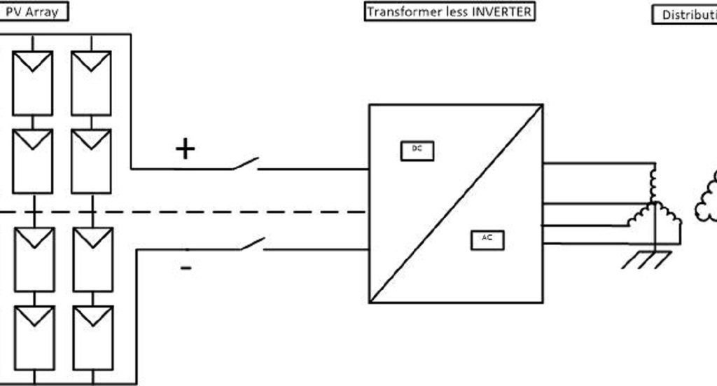
Figure 4: European Floating 1000 volt PV system
Although a floating PV array is not explicitly grounded, due to the grounded-neutral terminal on the inverter AC output, the ground potential will translate to the middle of the PV array. This means that as in the case with Advanced Energy inverter mentioned above, half of the array may be subject to PID.
Recovery from PID
The subject of recovery from PID was extensively studied by German scientist S. Pingel and his team. Pingel and his group concluded that “avoidance of harmful potentials leads to regeneration of affected solar panels. This recovery process takes time, and the rate depends on the electric potential and environmental factors such as humidity and temperature.” See figure 5 below for visual of this impact.
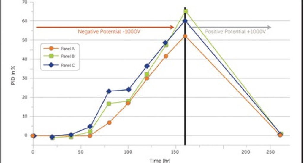
Figure 5: Recovery from the PID effect by applying proper grounding to PV modules
Alencon’s PID Cure
Alencon builds a galvanically isolated Solar Power Optimizer and Transmitter (SPOT) whose installation in an aged PV system can create the exact conditions that research states can, in many cases, reverse the harmful effects of PID (some PID may be so severe that is irreversible). The SPOT contains a set galvanically isolated DC -DC converters. The galvanic isolation feature allows the SPOT to reverse the polarity on the PV array, or part thereof, or change the grounding potential on the PV array without changing the polarity of the inverter input. This is done by grounding the input of the SPOT and the array connected to it in the manner most conducive to PID recovery and longer module life as recommended by the supplier, while still grounding the output of the SPOT in accordance with the inverter’s requirement.
Solution for Advanced Energy Inverters
To deploy the SPOT to reverse PID effects with Advanced Energy inverters, the SPOT DC-DC converter is installed between the positively-grounded subarray and the inverter. The SPOT then galvanically isolates that subarray from the negative inverter input. The negative terminal of this subarray is grounded (see Figure 6). This will eliminate PID conditions and eventually leads to the recovery of the effected PV cells.
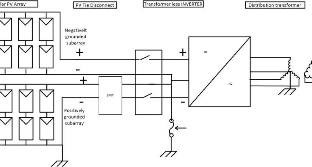
Figure 6: Alencon's SPOT reverses grounding of positively-grounded subarray in Advanced Energy systems.
Solution for Floating PV arrays
In the case of floating PV arrays like the 1000-volt European systems mentioned above, the SPOT should be placed between the array and inverter (see Figure 7). The array can then be properly grounded which eventually will lead to the recovery of the effected PV cells.
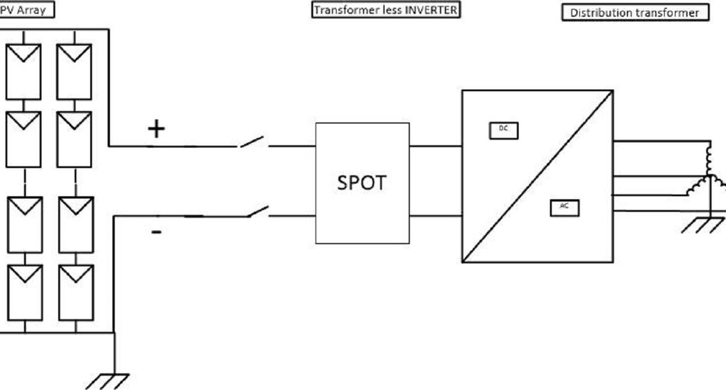
Figure 7: SPOT will reverse the effects of PID in floating systems.